
How to install a clamp spray nozzle is a controlled pipe-modification task: confirm compatibility, mark the layout, drill and deburr the opening, position the seal, seat the clamp, aim the spray and test the complete header. The exact hole and tightening requirements must follow the selected clamp’s documentation.
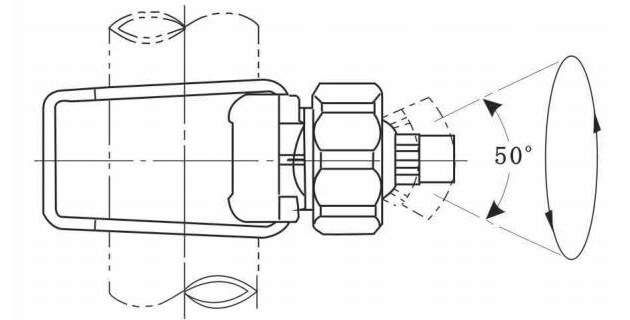
This procedure is a planning guide rather than a substitute for the clamp manufacturer’s instructions or site safety system. Work on an isolated, drained and verified safe header.
how to install a clamp spray nozzle: engineering checklist
This procedure explains how to install a clamp spray nozzle as a controlled mechanical and hydraulic assembly. Teams documenting how to install a clamp spray nozzle should record pipe OD, hole condition, 봉인 위치, orientation and the final leak and spray test.
Prepare the header before drilling
Installation quality is largely determined before the clamp touches the pipe. Verify that the pipe is structurally suitable for drilled openings, that its outside diameter matches the clamp and that the surface is clean enough to seal. Complete the nozzle layout so holes are not moved casually after drilling.
Engineering variables that change the decision
| Variable | Why it matters | What to record |
|---|---|---|
| Pipe identification | Wrong OD or unsuitable wall condition prevents reliable fit. | Measured OD, 재료, wall thickness and condition. |
| Hole position | Controls nozzle pitch, accessibility and pattern alignment. | Datum line, spacing and target direction. |
| Drilling method | Heat, burrs and swarf can damage the pipe or contaminate the system. | Tool, pilot method, chip control and deburring. |
| Gasket orientation | A displaced seal may obstruct flow or leak. | Correct side, centering and clean contact surfaces. |
| Nozzle alignment | Fan patterns require controlled rotation; adjustable balls require a repeatable aim. | Reference marks and target coordinates. |
| Test state | A static leak check alone does not validate spray coverage. | Dynamic pressure and all-nozzle operation. |
Installation steps
- Verify the clamp model against actual pipe OD, 재료, 액체, temperature and system pressure.
- Isolate, drain and clean the header. Establish a straight reference line and mark every nozzle location from the approved layout.
- Drill the approved opening while controlling chips. Deburr the inside and outside without enlarging the hole beyond the requirement.
- Flush or clean the header so drilling debris cannot enter nozzle passages.
- Inspect and position the gasket. Center the clamp inlet over the opening and seat both clamp halves evenly.
- Tighten using the approved sequence and method. Do not use uncontrolled force as a substitute for correct fit.
- Install and aim the spray tip. Mark the accepted orientation so future movement is visible.
- Restore pressure gradually, inspect for leaks, then operate all nozzles and verify coverage at the working distance.
Common failure modes and diagnostic checks
| Observed condition | Likely checks |
|---|---|
| Hole is off the layout line | Stop and assess coverage and sealing consequences before enlarging or redrilling. |
| Burr remains inside pipe | Remove it through an approved method and flush the header; loose swarf can block downstream nozzles. |
| Gasket will not remain centered | Check the correct gasket, pipe/clamp fit and hole geometry instead of forcing assembly. |
| Spray cannot reach the target angle | Review mount orientation and adjustment range; do not accept a strained hose or unstable clamp. |
| Header passes leak test but coverage is uneven | Run all nozzles and measure pressure, orientation and overlap under dynamic conditions. |
Validation and release checklist
Acceptance should include a dry visual inspection, controlled pressure test, full-header spray test and documented orientation. Where distribution matters, use a catch test or target grid. Reinspect after the first operating period for movement, seal settling and retained drilling debris.
- Confirm the selected component matches the pipe, 액체, 압력, temperature and mechanical environment.
- Test the assembled header for leakage, movement, flow balance and usable coverage.
- Record the accepted orientation, pressure and inspection criteria for maintenance.
- Keep product-specific limits and system responsibility with the approved drawings and supplier documentation.
Information to send with an RFQ
Provide the pipe outside diameter and material, wall condition, drilled-hole requirement, liquid and temperature, operating and maximum system pressure, target flow per nozzle, 스프레이 패턴, connection or tip preference, 노즐 간격, installation drawing, vibration or wash-down conditions and required maintenance access. Do not select a clamp from pipe nominal size alone.
자주 묻는 질문
Can the hole be drilled with the header in service?
아니. The header should be isolated, depressurized and prepared under the site’s approved safe-work procedure.
Is hand alignment sufficient for flat fan tips?
A visual check may be inadequate for uniform overlapping fans. Use reference marks, an alignment tool or a coverage test.
Should thread sealant be used on every tip?
Only use a sealant compatible with the connection, liquid and supplier instructions; prevent excess material from entering the passage.
Safety and next step
Before drilling, servicing or testing a pressurized header, isolate hazardous energy under the site procedure. For United States workplaces, consult OSHA’s Control of Hazardous Energy overview; local requirements may differ.
Explore industrial spray nozzle products 그리고 spray nozzle applications when defining the wider system.
Next step
Installation is complete only when the seal, flow and spray pattern have all been verified. Review the Jeltecn adjustable clamp spray nozzle, compare related 플랫 팬 스프레이 노즐, 또는 send the application data to Jeltecn for an engineering quotation.