
Dry fog dust suppression uses a fine spray close to the point where dust becomes airborne. For crushers, conveyors, screens and transfer points, the system must be designed around the dust-release location, enclosure airflow, available compressed air, water supply and acceptable material wetting. Jeltecn’s SK508, SV882 and SV980 data can be used to shortlist the nozzle; field validation is still required.
Quick design answer
Place the spray where dust is generated or first released, keep the zone as controlled as practical, and orient the mist with the process airflow. Select the model from its verified angle, approximate no-wind reach and air demand. Then test the installation under the actual material throughput and ventilation conditions.
Do not specify a universal “dry fog” droplet range or guaranteed moisture addition without a defined test method. The Jeltecn models have tested average droplet values of 10.02, 13.79 and 15.82 μm at their stated test heights; the result in a plant depends on the complete system and environment.
Verified ultrasonic atomizing nozzle data
| Model | Air requirement | Water requirement | Tested average droplets | Approx. no-wind distance | Angle |
|---|---|---|---|---|---|
| SK508 | 5.0 bar; 112 L/min | 1.0 bar; 0.359 L/min | 10.02 μm at 0.5 m | ≈2 m | 80° |
| SV882 | 5.0 bar; 240 L/min | 1.0 bar; 0.746 L/min | 13.79 μm at 1.5 m | ≈3.5 m | 60° |
| SV980 | 3.0 bar; 307 L/min | 0.5 bar; 0.688 L/min | 15.82 μm at 2.0 m | ≈4 m | 30° |
Droplet values are test averages measured at the stated heights. Distance is approximate under no-wind conditions. Strong process airflow can shorten or deflect the usable coverage.
SK508 is the widest listed pattern and has the lowest air demand. SV882 is a mid-width option. SV980 is narrower and reaches farther in the listed no-wind test, but it has the highest air-flow requirement.
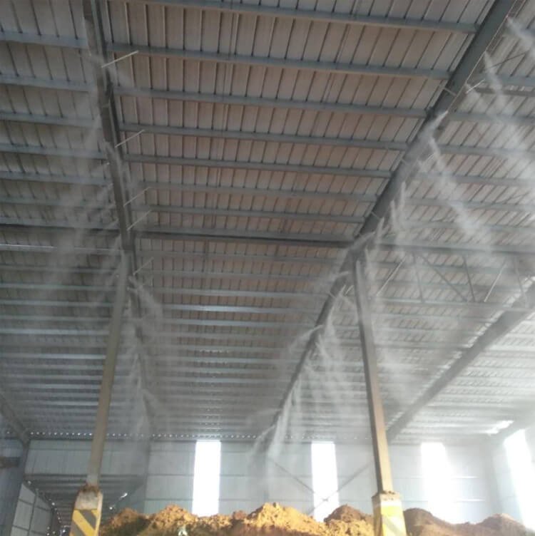
Where to position nozzles
Crusher feed or discharge
Identify the point where breakage or falling material creates the dust plume. Position the mist so it intersects the plume without being immediately blocked by material or surrounding steelwork. Use protected mounting and retain service access.
Conveyor transfer point
Focus on the receiving belt, drop zone and displaced-air path. A controlled enclosure can help retain the spray near the dust source. Avoid installing nozzles so far upstream that most droplets are lost before the material transfer occurs.
Screen, hopper or chute
Observe where dust exits the opening rather than spacing nozzles evenly by default. Multiple directions may be useful around a larger opening, but every active nozzle adds air and water demand that must be included in the header calculation.
Stockpile or open area
Open-air coverage is more sensitive to wind. The listed no-wind distance is only a starting point. A site trial should confirm whether the spray stays in the intended zone.
System design checks
| Design variable | What to confirm |
|---|---|
| Dust source | Exact release point, plume direction and operating cycle |
| Material | Throughput, temperature and acceptable surface wetting |
| Airflow | Enclosure ventilation, displaced air, cross-drafts and extraction |
| Compressed air | Pressure and continuous flow at maximum simultaneous nozzle count |
| Water | Pressure, total flow, quality and suitable filtration |
| Coverage | Required angle, reach, overlap and possible obstruction |
| Mounting | Common fixed adapter or thin-wall adapter, access and protection |
| Controls | Start/stop logic tied to actual material handling where appropriate |
Calculate simultaneous utility demand
Multiply the selected model’s per-nozzle air and water flow by the maximum number operating at one time. Check pressure under flow at the header, including regulators, filters, valves, fittings and pipe losses. See the installation and utility-sizing guide for the calculation and commissioning sequence.
Commissioning and measurement
- Record the nozzle model, quantity, mounting position and orientation.
- Measure air and water pressure while every intended nozzle is operating.
- Run the material-handling equipment at representative throughput.
- Observe the dust plume before and after spray activation from a safe position.
- Check drift, surface wetting, blocked coverage and pressure variation along the header.
- Adjust position or active nozzle count one variable at a time and record the result.
If the spray is weak, uneven or intermittent during commissioning, use the ultrasonic nozzle troubleshooting guide before changing the model.
Define the site’s acceptance method before the trial. Depending on the project, this may include visual plume observations, housekeeping frequency, process inspection or formal dust measurement by qualified personnel. Do not state a removal percentage unless it is supported by a documented site test.
Dry fog dust suppression RFQ checklist
- Equipment type and drawing or photos of the dust-release zone
- Material, throughput and operating schedule
- Enclosure dimensions and ventilation or extraction information
- Acceptable material wetting and nearby equipment constraints
- Available compressed-air pressure and continuous flow
- Available water pressure and quality
- Mounting distance, direction and access limits
- Outdoor wind or indoor cross-draft conditions
- Required controls and maximum simultaneous nozzle count
For model selection, compare the SK508, SV882 and SV980 range and review the engineering guide.