
Spiral nozzles can be considered for industrial dust suppression when the system needs broad wetting coverage and a comparatively open liquid path. The nozzle must be selected around the actual dust source, water quality, target area, pressure at the nozzle, wind or process airflow, runoff limits and maintenance access.
See the Jeltecn spiral spray nozzle product page for published sizes, angles and materials.
Start With the Dust-Control Objective
“Dust suppression” can describe different jobs. A spray directed at an airborne plume is not selected or positioned the same way as a spray used to wet bulk material before it drops onto a conveyor. Define the point where dust is generated and the result the spray must support before choosing a nozzle.
| Control objective | What to define | Why it matters |
|---|---|---|
| Source wetting | Material flow, target width, moisture limit and contact location. | Determines coverage, flow and placement. |
| Transfer-point control | Drop height, enclosure, air movement and available mounting positions. | Determines angle, orientation and spray distance. |
| Crusher or screen zone | Dust release point, vibration, access and equipment clearance. | Affects nozzle protection and maintenance. |
| Road or stockpile wetting | Area, wind, water availability, drainage and application frequency. | Determines total water demand and distribution plan. |
When Is a Spiral Nozzle a Candidate?
A spiral design is a candidate where full-cone or hollow-cone distribution, wide angles and an open discharge geometry match the installation. It may be useful when recycled or untreated water is used, but no spiral nozzle is universally clog-proof.
Maximum particle size, fibers, scale, biological growth, dried deposits and the selected orifice still affect blockage risk. Describe water quality and filtration instead of assuming an “anti-clogging” label removes the need for treatment and maintenance.
Dust Suppression Nozzle Selection Inputs
| Input | Required information |
|---|---|
| Dust source | Material, process, release point, airflow and operating cycle. |
| Water | Source, solids, maximum particle size, chemistry, temperature and filtration. |
| Hydraulics | Flow per nozzle and minimum, normal and maximum pressure at the nozzle. |
| Geometry | Target dimensions, spray distance, mounting position, nozzle quantity and overlap. |
| Limits | Maximum added moisture, runoff, freezing, corrosion and nearby equipment. |
| Maintenance | Isolation, flushing, inspection and safe replacement access. |
Pattern, Angle and Placement
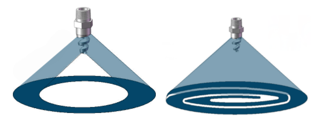
A full-cone spiral pattern is a starting point where the system needs liquid distributed through the cone volume. A hollow-cone pattern concentrates liquid toward the perimeter. The useful choice depends on the dust source and mounting geometry, not on the pattern name alone.
- Position sprays as close as practical to the defined source or wetting target without exposing the nozzle to impact.
- Check interference from guards, chutes, walls and moving equipment.
- Allow overlap only where the required water addition permits it.
- Evaluate wind and process air that can deflect the spray.
- Confirm that water does not create unsafe runoff or damage downstream processing.
Nominal spray angle is measured under defined conditions. The actual wetting footprint may change with pressure, liquid and airflow.
Published Jeltecn Spiral Nozzle Range
| Parameter | Published family range |
|---|---|
| Pattern | Full cone or hollow cone |
| Spray angle | 60°–180° |
| Thread size | 1/4–4 inch |
| Connection | Male or female; NPT or BSPT |
| Orifice diameter | 2.4–63.5 mm |
| Water pressure | 0.7–25 bar |
| Published capacity | 2.6–11,960 L/h; confirm model and pressure |
| Materials | 303SS, 316SS, brass and PVDF |
Flow and Pressure Checks
Measure or calculate pressure at the nozzle after filter, piping, valve and elevation losses. On a multi-nozzle header, confirm that the last nozzle receives the required pressure at total system flow. If a filter loads with solids, include the dirty-filter pressure loss in the minimum operating condition.
Choose the model from its flow table at the required pressure. Do not scale from the family maximum or assume that increasing pressure always produces the required dust-control result. The installed test must consider water addition, coverage and dust behavior together.
Water Quality, Filtration and Maintenance
- Size filtration from the selected nozzle and actual solids.
- Provide flushing points where branches can settle or dry.
- Inspect for scale, erosion, impact damage and changed spray pattern.
- Record baseline pressure and flow for comparison after maintenance.
- Use the site’s approved isolation and depressurization procedure before removal.
Common Problems and First Checks
| Problem | First checks |
|---|---|
| Dry section of the target | Nozzle position, angle, pressure, blockage, overlap and air deflection. |
| Too much water added | Flow per nozzle, nozzle count, control logic, leaks and operating time. |
| Frequent obstruction | Maximum particle size, filter, settling, scale and shutdown flushing. |
| Pattern changes over time | Deposits, erosion, physical damage and pressure drift. |
| Runoff or overspray | Placement, angle, spray distance, wind and total water flow. |
Dust Suppression RFQ Checklist
- Process and dust-generation point.
- Material handled and operating rate.
- Target dimensions, mounting drawing and photos.
- Water quality, solids, chemistry, temperature and filtration.
- Required or available flow and pressure at the nozzle.
- Added-moisture, runoff or freezing limits.
- Preferred pattern, angle, connection and material.
- Nozzle quantity, duty cycle and maintenance access.
For sizing, read the spiral nozzle flow and pressure selection guide.
Request a dust-suppression nozzle review
Site dust-control performance and occupational or environmental compliance require assessment by the responsible plant and safety professionals.